Installing universal standalone GCU requires certain modifications to be done to the mechatronics unit inside VW DSG DQ50 gen.2 transmission.
Actual for 1.0.9b-6 release
To modify it You’ll need:
- Soldering station
- Dremel /w abrasive plate
- Torx
- Side cutters
- Wires (24AWG silicone/PTFE wires, oil resistant, 200C rated)
CAUTION: This modification require soldering experience and steady hand due to very tight location of soldering
RECOMMENDATION: please use NOISE SUPPRESION circuit that can be found at HTG e-SHOP to minimize risk of signal noise. Circuit description can be found at WIKI / WIRING / NOISE troubleshooting
ANOTHER CAUTION: Gen.2 of DQ500 comes without clutch speed and temperature sensor by default! It has socket allowing to connect the same one as us!ed in Gen.1. This sensor canbe purchased here:https://htg-tuning.com/shop/dq500-shaft-speed-and-temperature-sensor/
After removing unit from valve body it is strongly recommended to degrease whole assembly to improve ease of modification and keep your workplace clean. Universal degreaser works just fine as well as brake cleaner or so.
- Perform following connections:

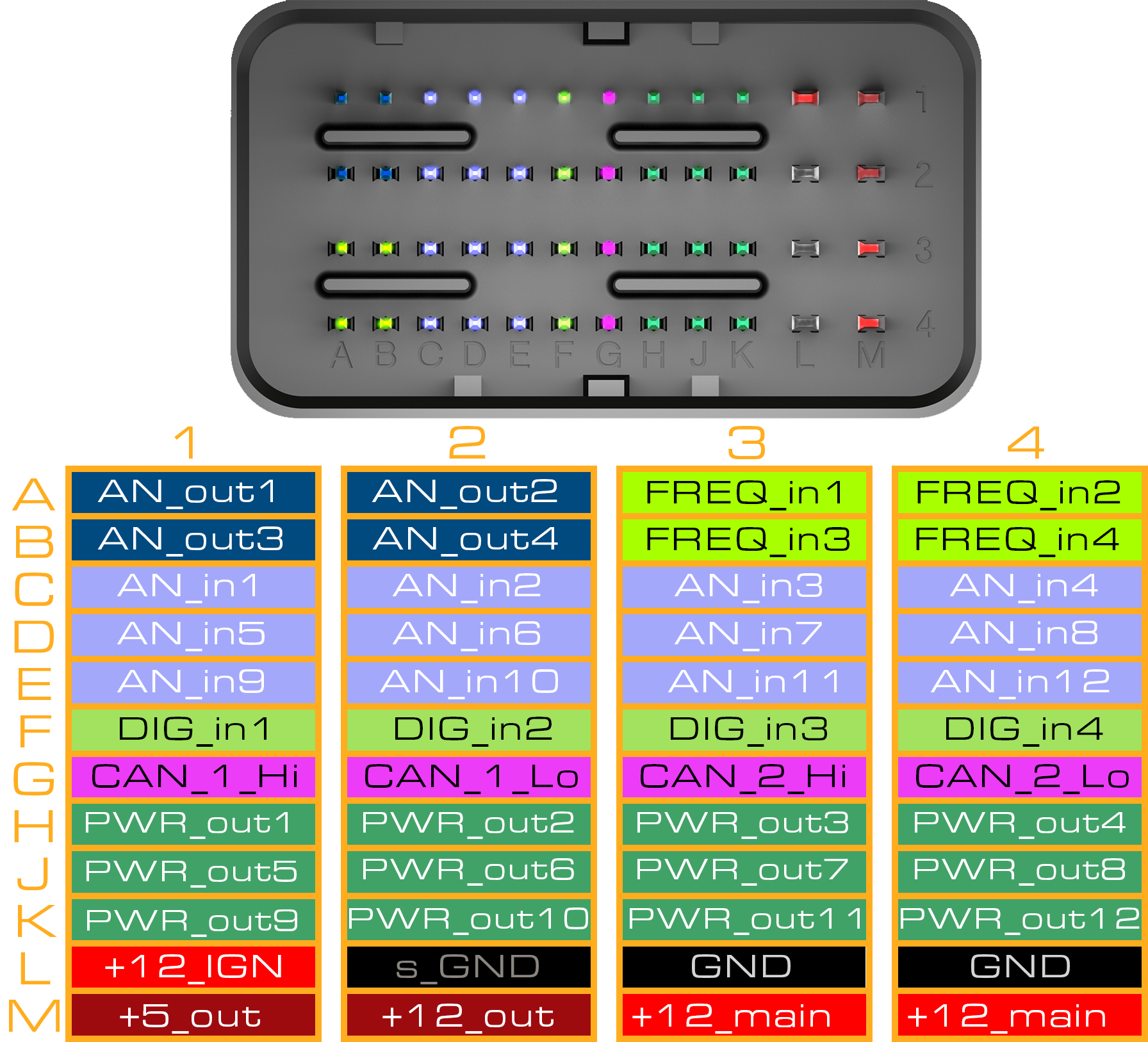
- A1 connect to GCU FREQ_in1 (A3) and add 82R (100R and 470R Parallel) pull-up to GCU +5v_out (M1)
- A2, A3, A8, A14, A16, B2, F1connect to GCU s_GND (L2)
- A6, A10, A12, A17, B3 connect to GCU +5v_out (M1)
- B1 connect to GCU AN_in2 (C2)
- F2 connect to GCU FREQ_in2 (A4) and add 82R (100R and 470R Parallel)pull-upto GCU +5v_out (M1)
- A4 connect to GCU AN_in8 (D4)
- A5 connect to GCU AN_in3 (C3)
- A7 connect to GCU AN_in7 (D3)
- A9 connect to GCU AN_in4 (C4)
- A11 connect to GCU AN_in9 (E1) and add 2k2 pull-up to GCU +5v_out (M1)
- A13 connect to GCU FREQ_in3 (B3)
- A15 connect to GCU AN_in1 (C1)
- From Solenoid side (S) :
- S1 connect together with S8 and S12 and connect to +12V_const (M3,M4)
- S2 connect to GCU PWR_out1 (H1)
- S3 connect to GCU PWR_out2 (H2)
- S4 connect to GCU PWR_out3 (H3)
- S5 connect to GCU PWR_out4 (H4)
- S6 connect to GCU PWR_out5 (J1)
- S7 connect to GCU PWR_out6 (J2)
- S8refer to point a.
- S9 connect to GCU PWR_out7(J3)
- S10 connect to GCU PWR_out8(J4)
- S11 connect to GCU PWR_out9 (K1)
- S12refer to point a.
- S13 connect to GCU PWR_out10 (K2)
- S14 is not used
Click here to see Interconnector pinnoutDo not forget to reinstall metal bracket holding Clutch Pressure sensors from behind. See below photo!
