Installing universal standalone GCU requires certain modifications to be done to the mechatronics unit inside this type of ZF 8HP transmissions. Test.
Actual for 1.0.9b-6 release
To modify it You’ll need:
- Soldering station
- Dremel
- Torx
- Side cutters
- Wires (1mm2 or 17AWG silicone/PTFE wires, oil resistant, 200C rated)
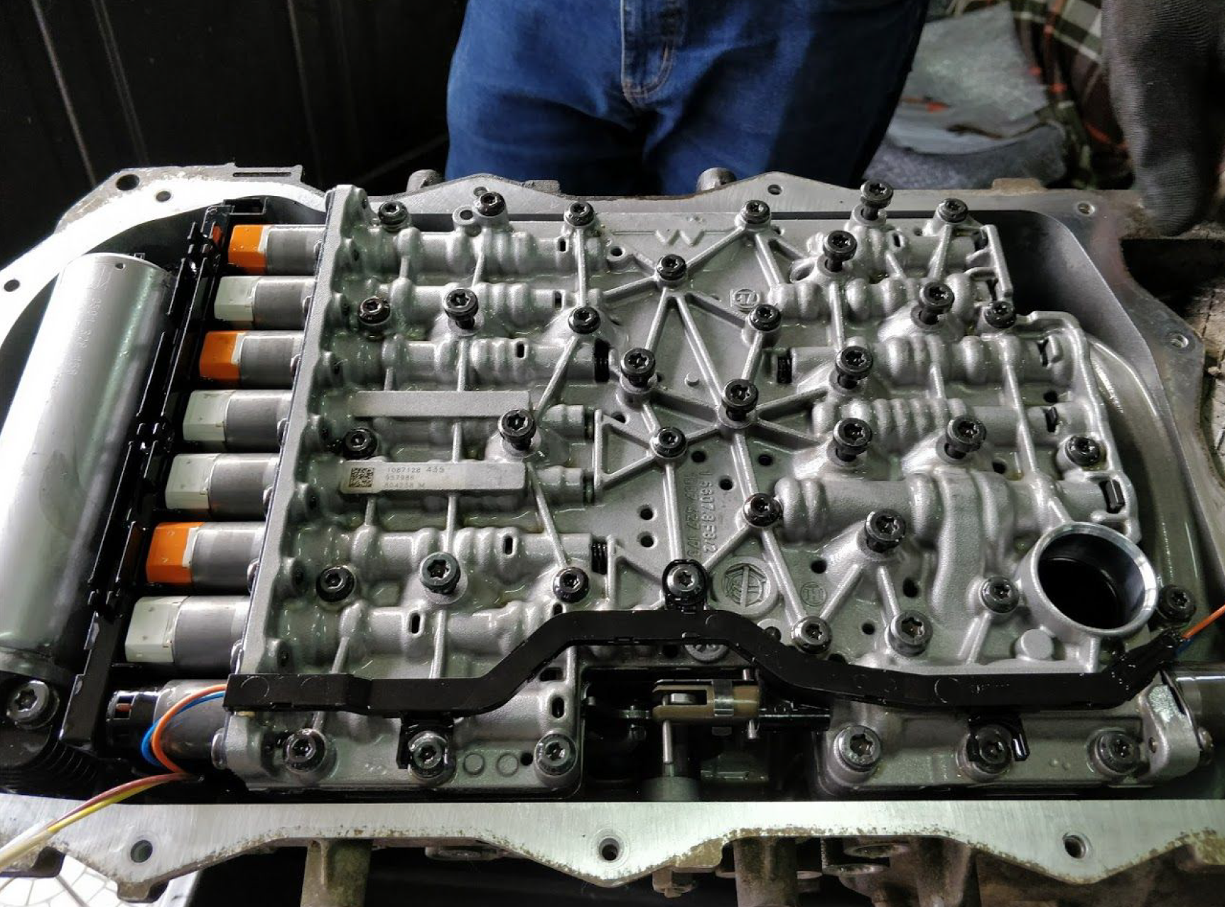
- Drain transmission fluid by removing screw in oil pan.
- Unscrew the plastic oil pan.
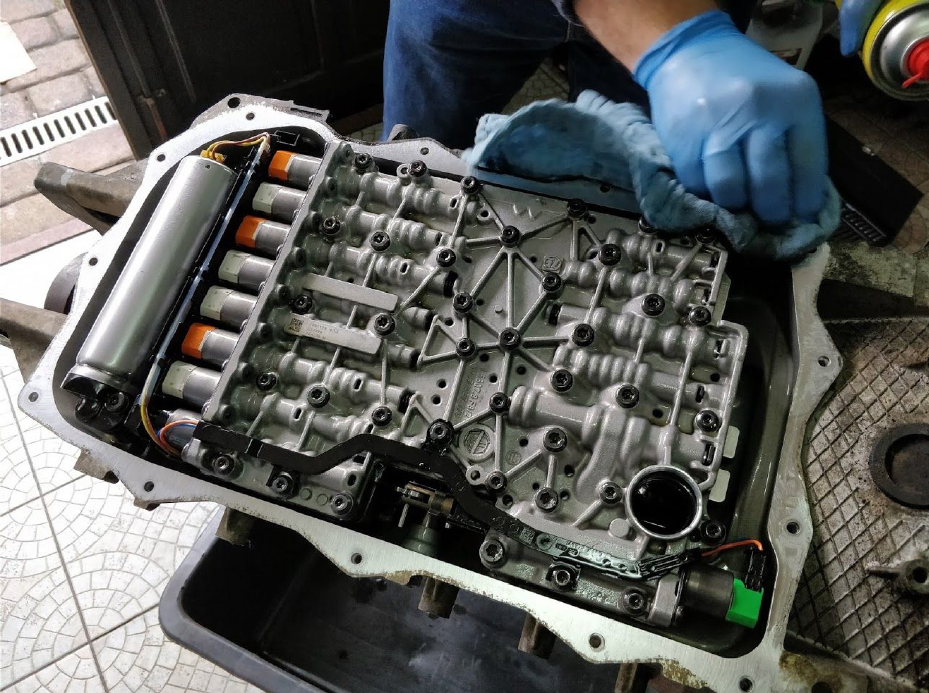
- Disconnect wiring connectors from solenoids and HIS.
- Pull a metal plate located on the opposite side to the pump to unlock round connector from the body.
- Unscrew mechatronics unit.
- Remove stock TCM from valve body. You’ll be able to see metal box. With grinder remove cap of box paying attention not to let grinder far inside this box to avoid damaging solder points.
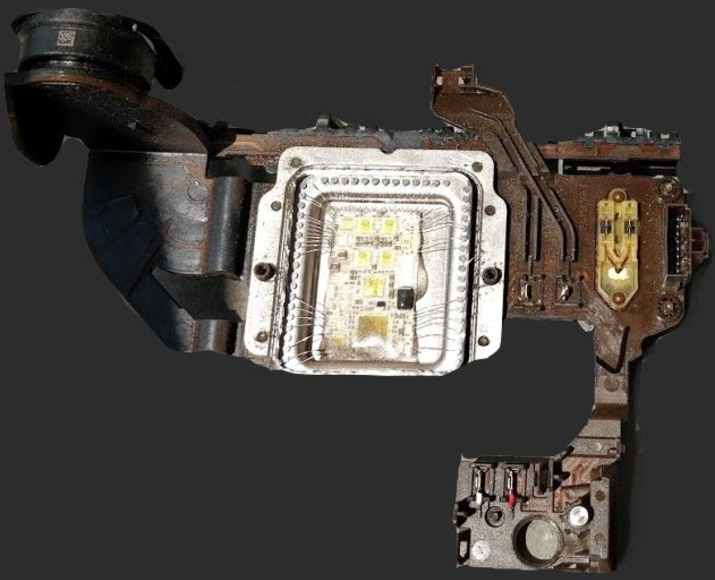
- Remove bondings from stock TCM to solder pads, and remove TCM itself with chisel.
- Solder wires according this scheme.
- Soldered area should look like on the picture below.
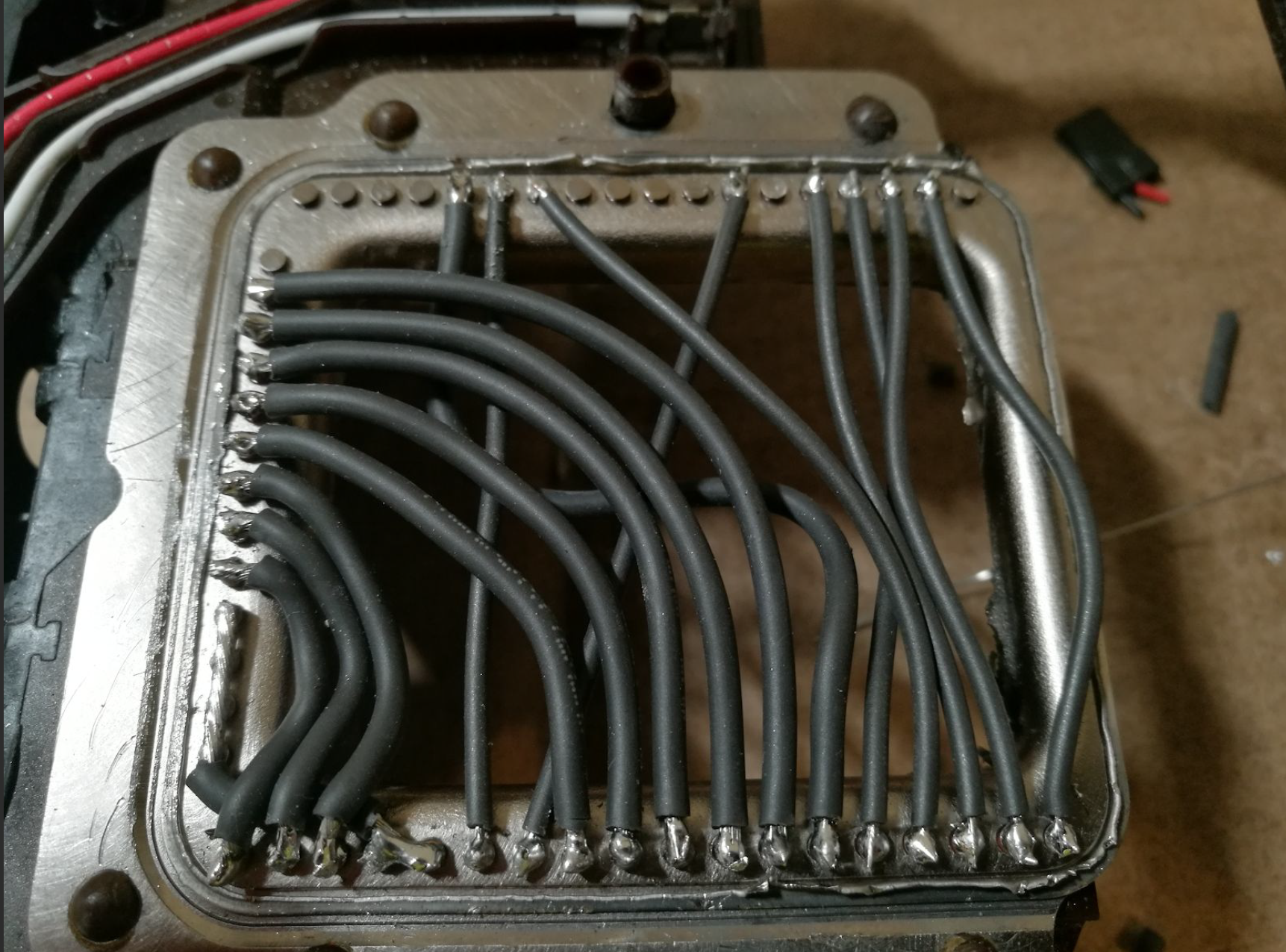
- Secure wires with silicone packaging to protect them from short circuits, and form moving inside of metal box.
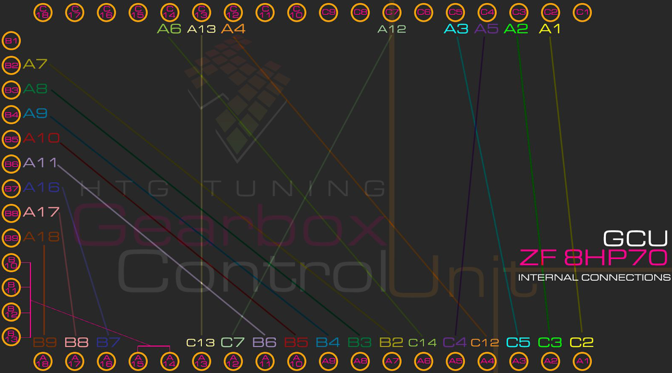
- Making such wiring inside allows to use case connector. To make patch loom GCU - transmission.
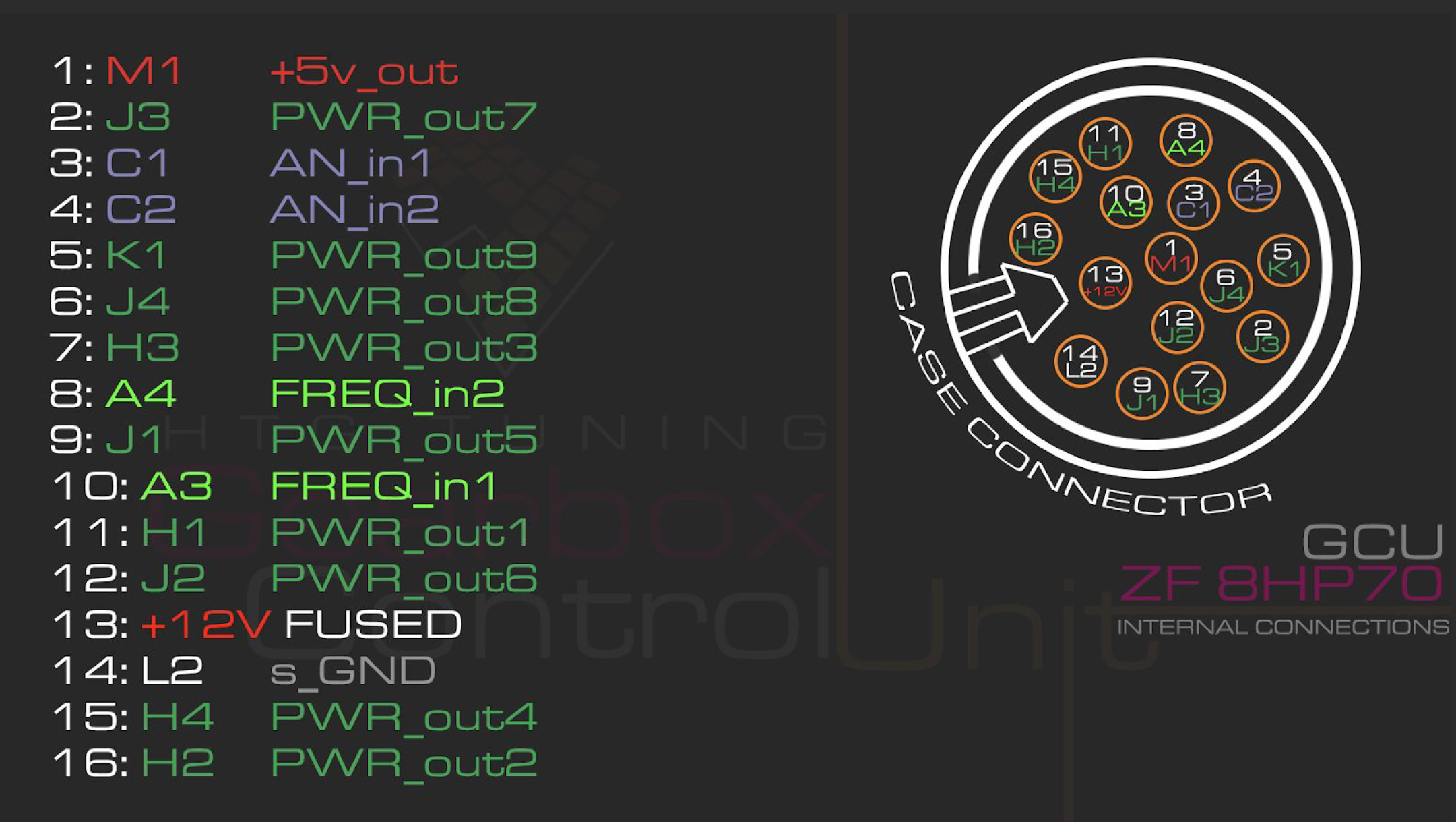
Patch loom should be made basing on above case connector and below GCU Main Connector pinout.
There is need to add pullup/pulldown resistors on following connections please put those resistors close to the GCU and make sure they aren’t vulnerable to mechanical damage:
- FREQ_in1 (A3) required 100R pull down to s_GND (L2) at GCU end
- FREQ_in2 (A4) required 100R pull down to s_GND (L2) at GCU end
- AN_in1 (C1) requires 2k6 pull up to +5v_out (M1) at GCU end
- AN_in2 (C2) requires 500R pull up to +5v_out (M1) at GCU end
HTG GCU requires main (MAIN RELAY’ed) battery +12v applied to +12_const (M3, M4), as well as ignition +12v signal applied to +12_IGN (L1).
Even though HTG GCU has internal protection it is advised to secure IGN signal with 5A fuse to prevent failure of the device.
Ground connections GND (L3 and L4) should be made on engine or chassis, as long as chassis ground point is confirmed to be efficient.
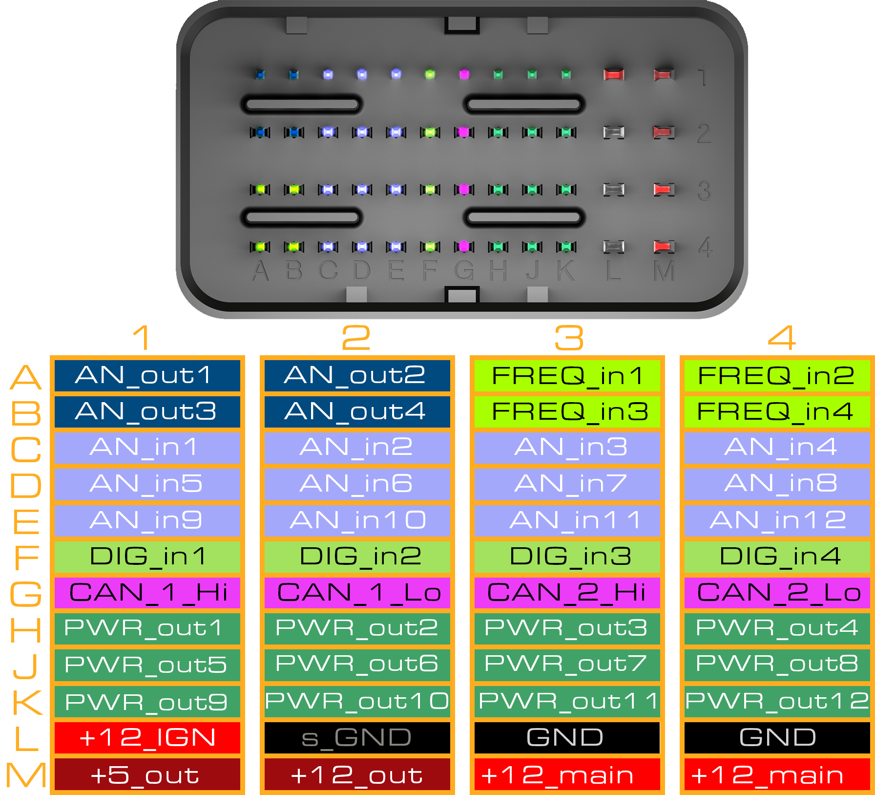
For proper functionality HTG GCU needs to be fed with ECU signals. Those signals are used to configure and map transmission operation.
To communicate with ECU AN_out1-4 (A1,A2,B1,B2) can be used as CAN_1 and CAN_2